While working on JMPM, I ran into the exact same problem described by everyone else who has built a current sensor around the SCT013. JMPM is based on the references at OpenEnergyMonitor and they have a great article on the performance of measuring low currents. When I designed my circuit for Jm Power Meter (JMPM), I took their word at face value but what was discovered was they are only partially correct. I have found one fundamental flaw in the reference design and another flaw in the actual construction of the SCT013. There are dozens if not hundreds of DIY current monitors that is based on OpenEnergyMonitor. With the addition of one additional component per sensor, we can achieve a nearly 3x improvement on our low current measurements.
Table of Contents
Problem Statement
The accuracy of our measurements with the SCT013 are extremely poor when measuring very low currents but spot-on when measuring higher currents.
Test Procedure
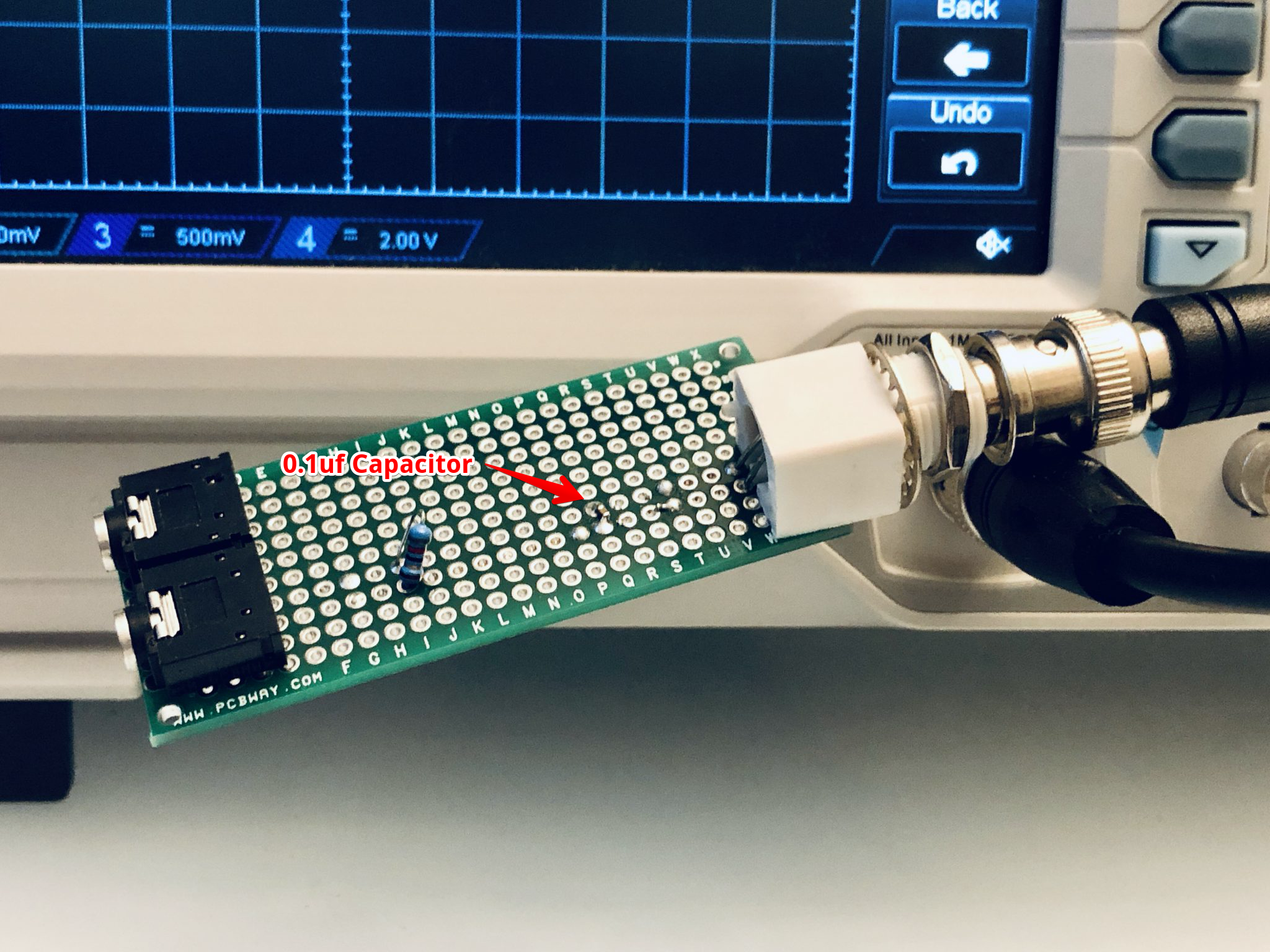
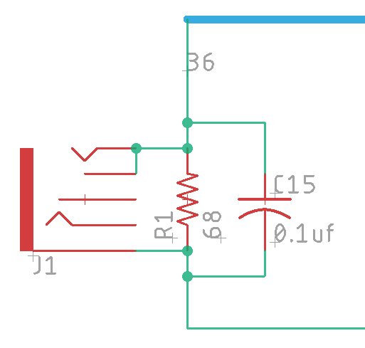
To properly quantify, qualify and troubleshoot the noise, I create a very simple test rig. It’s nothing more than an 1/8″ audio jack directly wired to an BNC connector with an 82ohm burden resistor. Since I’m going to be measuring very low voltages, the signal path to the oscilloscope must be extremely clean.
With the test device in hand, I’ve defied 4 test scenarios across two different conditions. The first condition uses the test circuit as as and the other uses a 0.1uf 0603 ceramic capacitor soldered in parallel with the burden resistor. An earlier version used an electrolytic capacitor, but the resistance of the electrolytic capacitor added to the burden resistor and changed our results too much. We will be focusing on the Peak to Peak voltage (Vpp) of the output signal.
I left out the part of the circuit responsible for changing the bias of the output AC signal to fit within the range of a 0 .. 3.3VDC or 0 .. 5VDC measurement range. The oscilloscope measures AC directly, so we don’t need to rebias the signal with a “virtual ground”.
Data & Test Results
| Vpp – Peak to Peak – No Filter Capacitor | Vpp – 0.1uf Ceramic Capacitor | |
| No Load – No CT attached | 5.4mV | 1.2mV |
| No Load – CT attached | 8.6mV | 2.6mV |
| No Load – Holding the cable with my hand | 18.0mV | 8.4mV |
| 12.5A Load – CT attached | 1.48V | 1.48V |
I did try other values for the filter capacitor, ranging from 0.01uF to 1.0uF and saw very little difference in the results. I ended up performing the evaluation with 0.1uf for no reason other than I have a lot of that value in my kit.
Let’s take a look at the waveforms side by side.
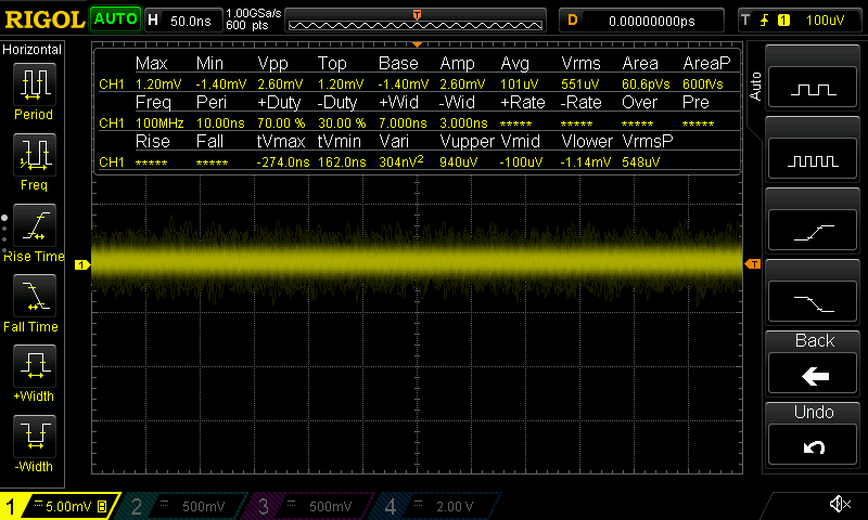
| No Load – No CT attached | |
| Vpp – Peak to Peak – No Filter Capacitor | Vpp – 0.1uf Ceramic Capacitor |
 |
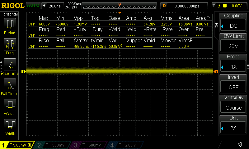 |
With no CT clamp attached, this is our true no load situation and is our baseline.
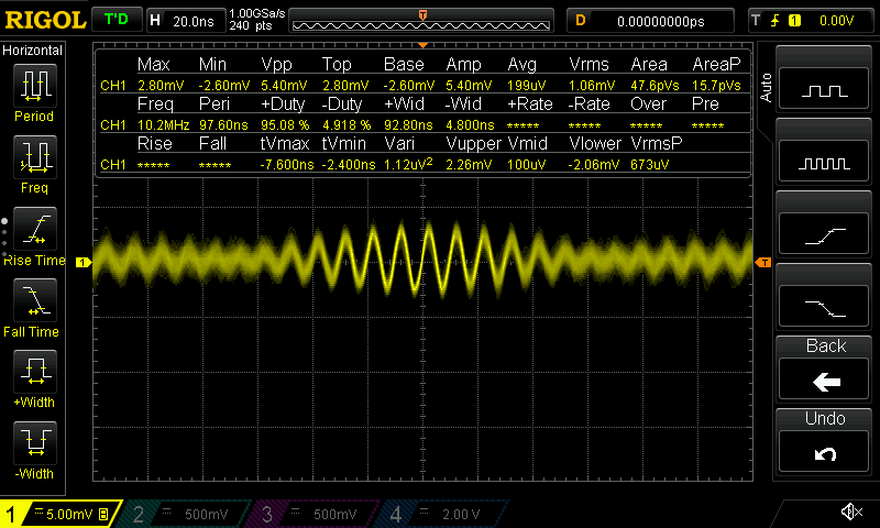
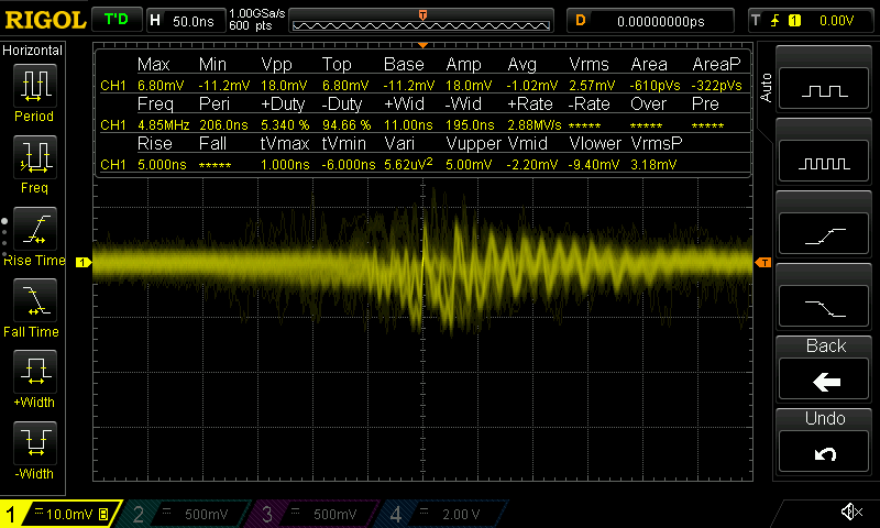
| No Load – CT attached | |
| Vpp – Peak to Peak – No Filter Capacitor | Vpp – 0.1uf Ceramic Capacitor |
 |
 |
Wow, just wow! That’s a huge difference in the noise of when an unloaded CT sensor is attached to our device.
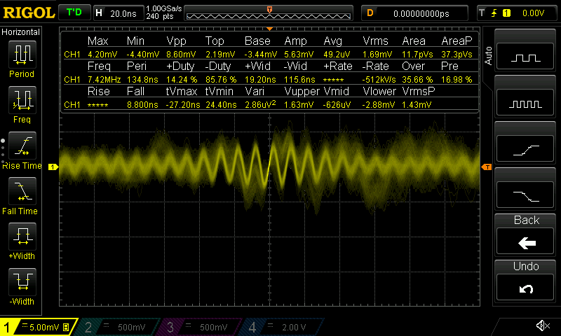
| No Load – CT attached, holding the cable with my hand | |
| Vpp – Peak to Peak – No Filter Capacitor | Vpp – 0.1uf Ceramic Capacitor |
 |
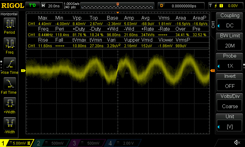 |
In this test, I hold onto the insulated cable with my hand. My hand is not in contact with any of the conductors. Why is there so much more noise when we hold onto the cable with our hand? Let’s explore this more later.
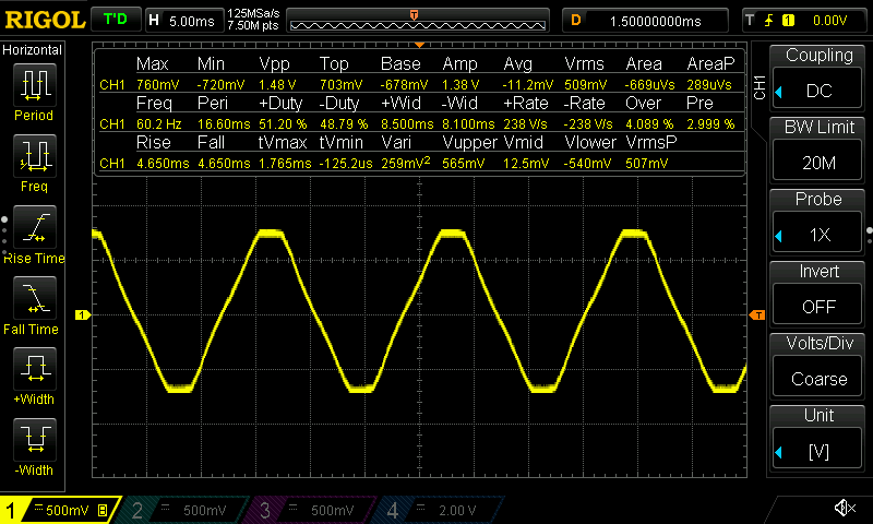
| 12.5A Load | |
| Vpp – Peak to Peak – No Filter Capacitor | Vpp – 0.1uf Ceramic Capacitor |
 |
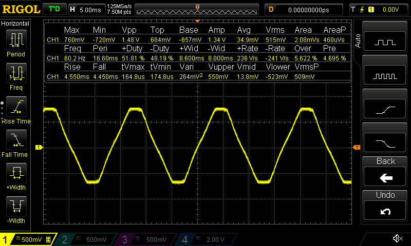 |
This confirms our observation about taking readings from the CT sensor when it is loaded up. When I have my 12.5A (1500W) office space heater turned on, there is no noticeable noise in the signal. The noise is actually still there, but the scale of the signal in relation to the noise floor is such that the noise can be ignored.
Why does my hand induce noice?
One of the curiosities I read on several websites was that placement of the CT sensor and the other devices around the sensor may change the readings from the sensor. This suggested to me that something was acting as an antenna. The performance of an antenna can be manipulated by holding onto the antenna. Doing that with the CT sensor does, in fact, induce nose in the readings. Why does this happen?
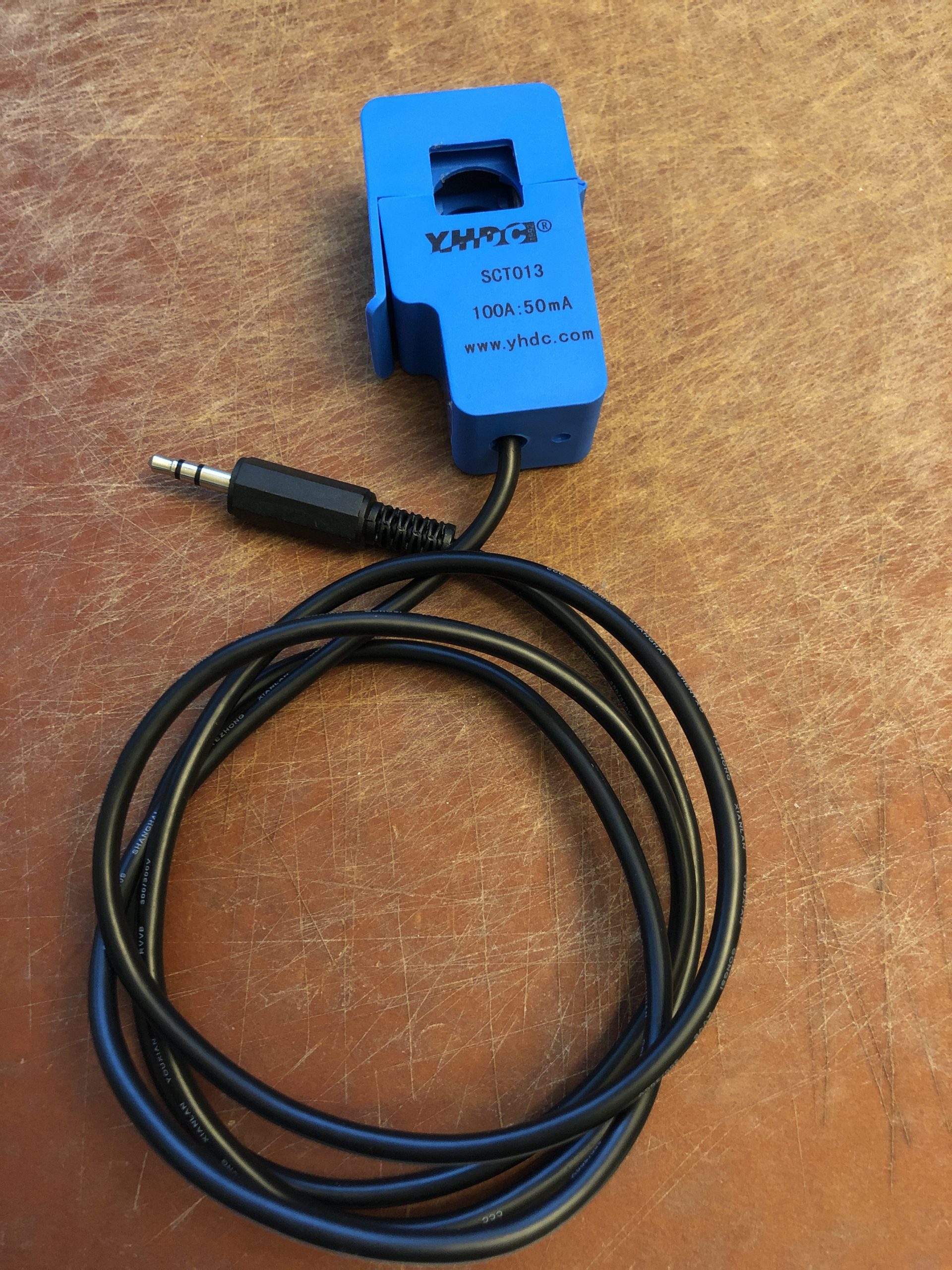
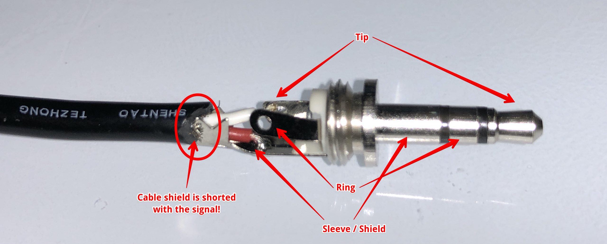
I was prepared to take apart the CT sensor but took the easy approach of first opening the housing of the 1/8″ barrel connector to see how this was manufactured. What I found was totally embarrassing but I should have guessed that this was the source of the problem.
The CT sensor uses the sleeve of the connector to carry the signal. As assembled, the signal (red wire) is shorted out with the cable’s shielding. This means that the shield acts like a 1 meter (3ft) antenna. I have a box of 25x of these sensors and on examination, each and every one of them has this defect.
Ideally, the white wire is soldered onto the tip. The red wire onto the ring and then cable shield is soldered to the sleeve of the connector. The measurement device can then be designed to properly ground the shielding, thereby rejecting a significant amount of induced noice.
The lowest effort approach is to mitigate the noise with the inclusion of a 0.1uf filter capacitor as we have demonstrated. Slightly more effort would be to resolder the 1/8″ barrel connector and making sure that the cable’s shielding is not shorted with the signal wire. The best solution, but one I don’t believe is worth the effort, is to change the pin out of the CT sensor to give the sensor’s shield a path to ground.
I suspect the CT sensor is assembled this way is to save a few seconds for the hand soldering of the connector. This probably saves the person hand-soldering this about a minute.
Conclusions
With just 2 hours of work, which includes the time to write this article, we have come up with two conclusions. Hopefully with this information, other people can take the steps to address this in their own projects.
Filter Capacitor Needed
OpenEnergyMonitor has done a lot of work for us, but they missed the inclusion of a small value capacitor to filter input noise. I checked not only their reference design, but the schematic for their v3.0 energy monitor. The capacitor is missing from there too.
If you’re going to build this for yourself, be sure to include a filter capacitor parallel with your burden resistor.
Poor Design of the CT Clamp
The SCT013 has done a lot of things right but it’s clearly built to a price point rather than for quality. I suspect the reason was a cost reduction consideration, but it was a very poor choice considering the overall design of the clamp.
As stated above, there are multiple fixes for this. If you want an easy fix — just include the filter capacitor and be done with it. If you want slightly more effort, ensure the cable’s shielding is not shorted with the signal. Even more effort would be to use the cable’s shielding as intended — to shield the signal rather than to induce noise to the signal.
Notes
My test jig has two 1/8″ connectors. The second is unused. I was going to build two circuits on the perf board, one with capacitor and one without, but I only had one spare BNC connector. I didn’t want to spend any extra money for this.
I used an 82ohm resistor for the jig because that’s the first resistor I pulled out of the bin. My circuit uses a 68, so it’s close enough. I know the reference designs uses a different value, but I’m interest in a different measurement range.