The first batch of JMPM Hardware Rev001 was delivered last week. After some initial testing, the board was found to be rather functional. One signal for each CT sensor was misrouted, but this is easily fixed with a jumper wire. Having the prototype also allowed proper characterization of the circuit and can be improved on by the inclusion of an optional low pass filter.
Build
Assembly can be completed in under 10 minutes per board. To save time and effort, be sure you have everything you think you’ll need before you start.
Bill of Materials
| What | Link | Notes |
| ESP32 Development Board | https://amzn.to/3bK1siJ | Get more than you think you’ll need incase one fails. It’s unlikely, but it’s good practice. You can get these for about $5 each if you get them directly from Chinese sources, but be prepared to wait a long time and expect the possibility of counterfeit products. |
| 3.5mm Jack Socket | https://amzn.to/3cGfiUP | Each board needs 5 sockets, but if you don’t plan on using all 5 sensors, you don’t need to install all 5 sockets. |
| CT Sensor SCT-013-000 | https://amzn.to/3fXCbF8 | You’ll need one for each circuit you are going to measure. |
| Female Header | https://amzn.to/2LDCtTW | (Recommended) This will make it easy to swap out your ESP32 development board. |
| Power Connector | https://amzn.to/2yfRh8c | (Recommended) These terminal blocks will let you easily plug/unplug your device. |
| Power Adaptor | https://amzn.to/2Zef9E0 | (Recommended) Any voltage from 5-14vdc will work. Ideal is around 7vdc. Use what you have. |
| Enclosure | https://amzn.to/2TcSuEf | (Optional) Box for the device. Everything will fit inside. You’ll need to drill holes for the various ports. |
| Breakaway Headers | https://amzn.to/3cBm2mR | (Optional) Only needed if you want to use a jumper to reconfigure the inputs to the expanded 120A measurement range. |
| Jumper Caps | https://amzn.to/3g7XpAu | (Optional) Only needed if you want to use a jumper to reconfigure the inputs to the expanded 120A measurement range. |
| 4-Pin Keyed Connector | Jameco 152726 | (Optional) Header for temperature sensor. You can also use the breakaway headers or leave it out entirely. |
You may find these items cheaper from other places like eBay or AliExpress. I’ve seen counterfeit products on eBay, so be careful. I have not gotten counterfeit items from AliExpress, but they are slow. Stay away from wish.com!
The BOM above doesn’t include quantities. Buy what you need. You may also have the parts in your drawers. Most of those are very common.
Note: The amazon links are affiliate links.
Assembly Notes
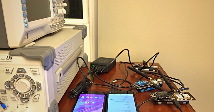
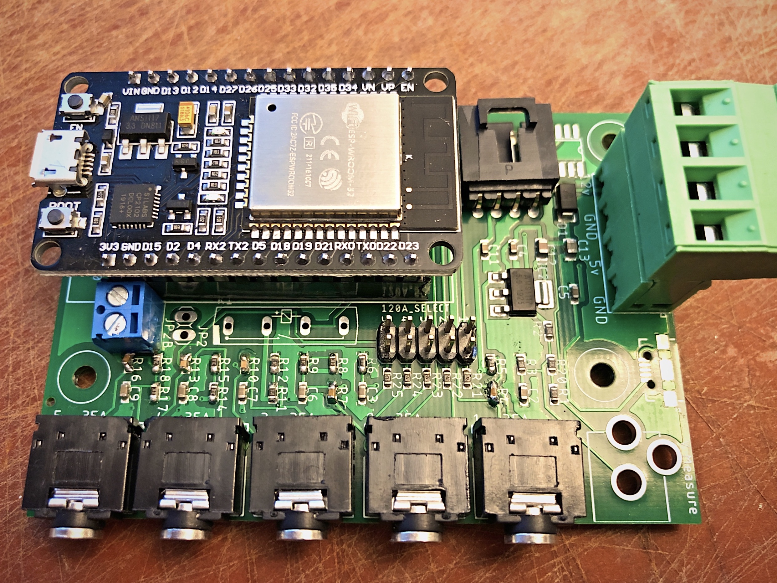
Use the featured image above as your guide for assembly. It’s always best to solder components from the shortest first and work your way up from there.
If you don’t ever plan on measuring more than 35 amps, you don’t need to install the header for on the 120A select jumpers. Use a jumper cap to hold the headers together at the proper width. Alternatively, you can solder a jumper wire across the pins of the 120A Selection block if you want to always measure 120A … but don’t do that if you can avoid it.
CT Connector
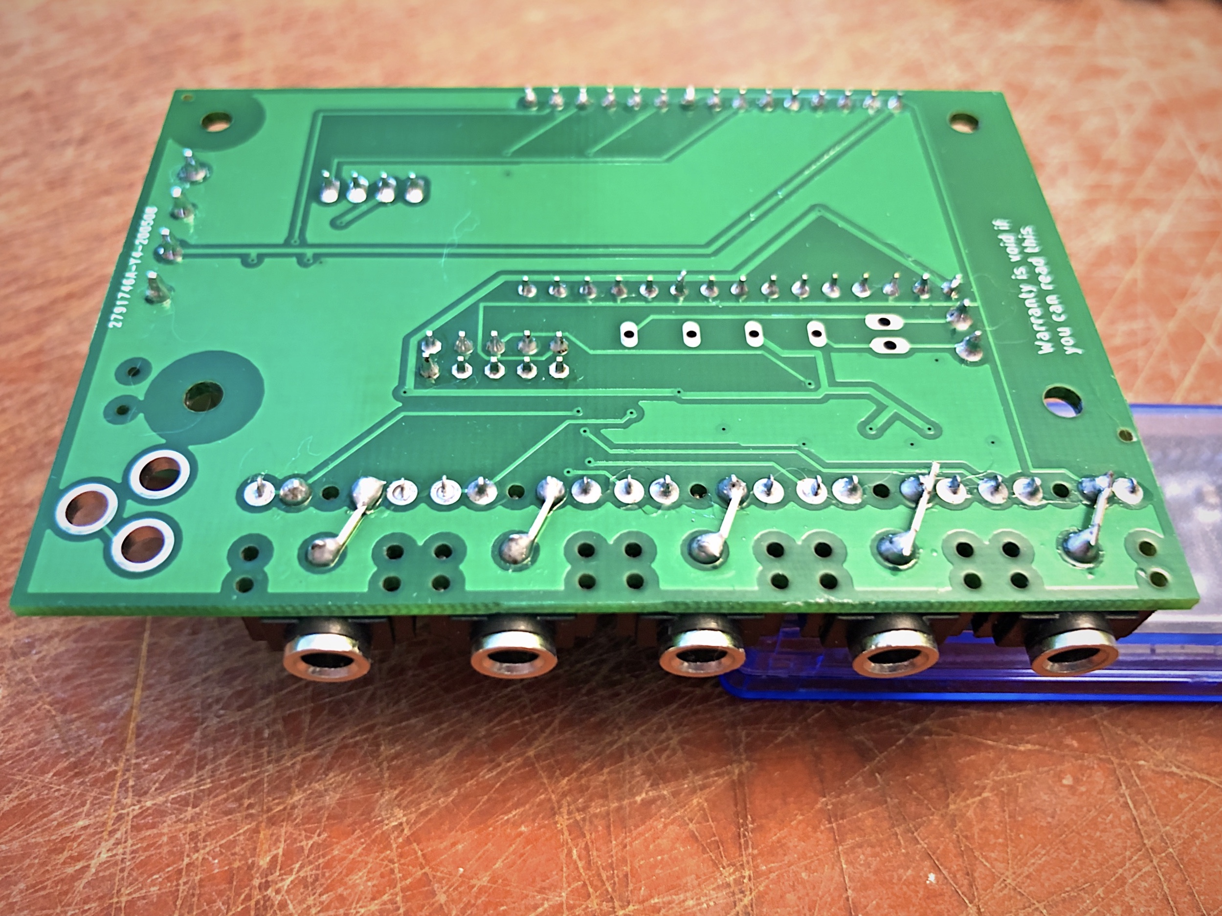
I made a mistake in routing the nets on the schematic for Rev001. To fix this, add a jumper wire on the back of the circuit board to connect the Tip to the Sleeve pins of the input connector.
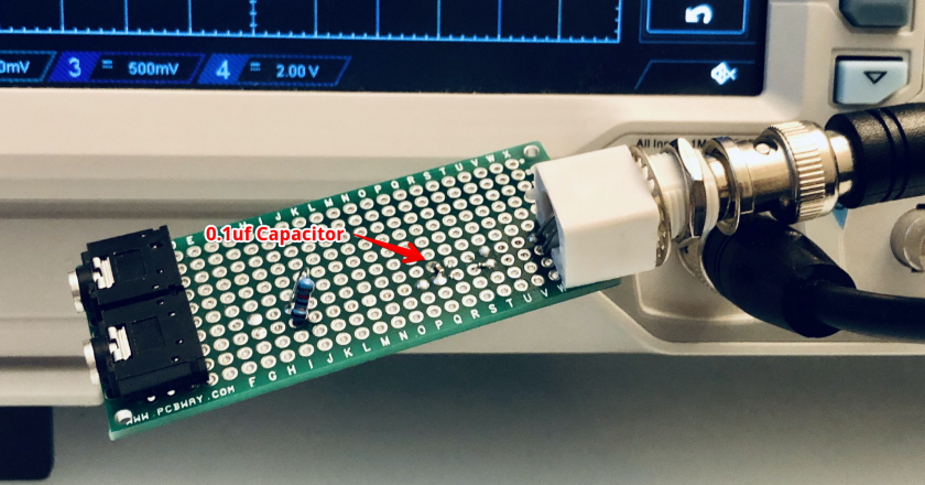
Low Pass Filter
Schematic
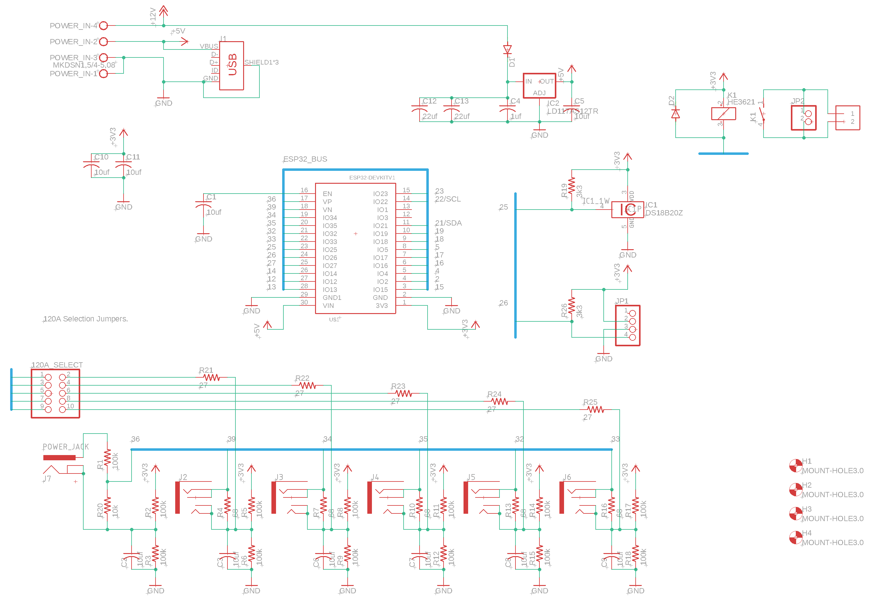
Click on the image to zoom in.
Power Up
The board can be powered in one of three ways:
- (Preferred) 7-14VDC power supply
- Connect a 7-14VDC @ >250ma power supply to the power header. This is preferred since this provides the most amount of filtering. It really is overkill, but do it if you can.
- 5VDC power supply
- Connect a 5VDC @ >250ma regulated power supply to the power header.
- MicroUSB
- Plug a MicroUSB cable to the ESP32 dev kit. This is the least preferred method because this connector is fragile. Functionally, there’s no difference between this and #2 above.
Firmware
The latest firmware can be found in GitHub at:
Read my post on how to install the Arduino IDE and ESP32 board files:
Enclosure
The enclosure on the BOM is untested, but the CAD drawings suggest it *should* fit. You’ll need to drill holes for the various sockets for the sensors.
If you do plan on using to measure current of circuits in your electrical panel, just remember that this can not be mounted inside the electrical panel. It has to be mounted outside the panel.
- Board Dimensions: 2.225″ x 3.225″
- Current Connector Spacing: 0.525″ on center
Notes & Errata
- The voltage sense input is currently untested. I’m probably going to take it out of rev002.
- The temperature sensor connector is currently untested. It *should* work.
- You can leave K2, JP2 and JP2B unpopulated. I have those there to control my hot tub.